October 2008
Friday 10th October 2008
It's been a while since I last put an entry into the Hog's diary, so here is a quick resume of the last year.
Following the self destruction (yet again) of the motor controller during a demonstration to one of the local village youth clubs, I decided, after some soul searching, to save the Hog from the scrap heap and to repair the controller once again. For whatever reason, the MOSFETs were blowing up, so I wanted to find a way to save them each time something went wrong. I had previously used some "protected" MOSFETs to create a current limiter, so decided to use these in place of the high current H bridge MOSFETs. The problem was that the protected MOSFETs current limit at 40 amps, which meant that each H bridge branch would only handle 160 amps instead of the 500amp they currently did. However, this would mean that at least things shouldn't overload and blow up. It also meant that the motors would not be running at their maximum power. However, I was running out of the now obsolete high current MOSFETs, so there was little choice about what to do. I bought a full complement of "protected" MOSFETs and replaced all those on the H bridge.
With the controller refitted, I tried out the Hog without any load. All seemed okay, and the wheels span fine in both directions. However, when I put the Hog on the ground and tried to drive it, the Hog barely moved. I felt the MOSFETS and they were very hot. I realised that they were thermally shutting down because the motors were presumably drawing too much current. It then dawned on me that maybe the gear ratio I was using in the transmission was not high enough. I was using a 9.6:1 gear ratio, which probably wasn't enough. The main reason I had used this ratio was because it used the largest sprocket I could find on the wheel drive shaft, and the smallest one on the motor shaft. Other than that, I had not done any proper calculations.
I know that many other roboteers used gear ratios almost twice this value. With the low ratio I had, the motors would run too slow, and consequently draw excessive current. I really needed to add an idler gear in the transmission to increase the gear ratio and thereby reduce the current drawn. It would also mean I would have more pushing power, and make the batteries last longer, so I set about fitting an extra idler gear on each transmission.
Friday 17th October 2008
I bought a selection of sprockets from Technobots and offered them up in the space I had left in the body of the Hog. I settled on using a 12 tooth sprocket on the motor, and a 30 tooth sprocket on the idler shaft. I could keep the original motor sprocket and attach it to the other end of the idler shaft so that I would now have an overall gear ratio of 28:1, which should be a lot better than 9.6:1! There was not much room to spare in the Hog's body, so I decided to use a counter lever mechanism to support the idler shaft from one side only. I would use two small bearings side by side, supported in an aluminium case to support the shaft. Below are some pictures of the idler shaft, the gears, and the support housing.
 |
 |
 |
 |
|
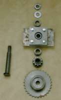
Raw metal for the bearing support block and ider shaft, together with bearing |
Exploded shaft components |
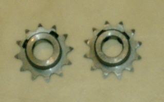
Bored out motor sprockets with locking grub screws |
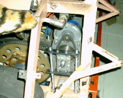
Idler shaft in situ in Hog |