March 2002
Saturday 2nd March 2002
I finished building the front flipper framework, and then mounted the rams on it as well. It wasn't until gone midnight that I finally had the job complete, so I couldn't check its operation. However, I did put the Hog on the scales and bearing in mind that all the functional parts were on the robot, I was pleased to see it weighed under the limit at 96kg. This wouldn't leave me enough weight to fully clad it, so I will have to get the hacksaw out and cut some metal off.
Sunday 3rd March 2002
I tried out the flipper today, but had to fiddle with the CO2 pressure regulator a bit first in order to get it up to full pressure.
| I had designed the pneumatics and controller such that the flipper would initially lift up at full speed by de-pressurising the top side of the ram. Once up, restrictors would be switched into the exit pipes, which would ensure a controllably action in either direction. Only when the flipper was fully down again would a micro switch sense it was fully down, and then switch the exit restricts out of circuit once more. This means it was now armed for a quick open action next time. I was very pleased that all the design and planning of previous months had paid off, and the flipper behaved just as I had planned! | 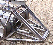 |
I checked the self-righter too, and noticed that the action was very sensitive to the pressure in the system. It was noticeable that the regulator did vary the pressure as it cooled during use, and there were a few times when it just couldn't quite right the Hog, leaving it stranded on its back.
Below are some shots of the Hog with its new flipper. Note the bottom right picture with a frosty CO2 bottle after I had done some flipper tests.
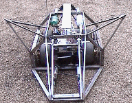 Front view |
 Front side view |
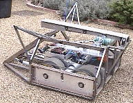 Rear side view |
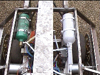 Frosty CO2 bottle |
In the afternoon I trimmed down the tail a bit to reduce its weight, and also moved the self-righting ram to give it a less acute angle to the tail. This would give it better mechanical advantage while righting the Hog, and hopefully would make it less sensitive to pressure variation in the system. The only side effect was that the tail is slightly raised when at rest instead of being horizontal, but this didn't seem to be a problem.
A friendly neighbour popped his head over the garden gate while I was trying it out, and identified a position where he thought it would be stranded on its rear side buttock. I rolled the Hog over and found that indeed there was a position I had not intended it to get stranded in. I could either weld a couple of small lengths of tube to stop it resting in this position, or as it turned out, the flipper would just topple it back onto its wheels, so I needn't do anything. Guess which option I went for!
Friday 8th March 2002
I wired up the buddy box and tried it out in the garage with partial success. I suspect that as I'm extracting some of the sensitive wired from their nice shielded surroundings in the transmitter, they are picking up general interference. It was noticeable that the actuators flickered as I moved my hands over the buddy box and wires. I think my approach will be add loads of decoupling capacitors at various points to snub out the jitter I am getting.
Saturday9th March 2002
| Today was the first real try of the Hog in a large arena type area. The family pushed the Hog down the street to the local infants school playground, which must have been a 100 ft square area of tarmac. The results were mixed with some good and bad points appearing by the time the batteries became flat. | 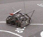 |
On the positive side, I managed to flip a go-kart wheel about 12 feet into the air once I got the flipper under it in the right place. I also managed to self right it after I had played about with the gas for a while, so the new tail position seemed to be okay.
However, the main downer was that steering became difficult after only a minute or so, and the batteries weren't able to last more that two or three minutes before the Hog only trundled along slowly in a straight line. The reason for the loss of steering was the traction the go-kart wheels had on the tarmac. The Hog's two sets of wheels on each side acted as "tram rails", making the robot want to go straight easily, but causing an awful lot of friction when trying to turn. This wasn't noticeable while testing the Hog in my front garden because of the gravel pathway. On tarmac the added friction caused the motors to draw a lot of current during turning, and consequently cause the batteries to quickly loose power.
It was strange that although I couldn't get the Hog to turn, if I manually pointed it across the playground, it would go straight as a die under power, not particularly fast, but it was still mobile.
The solution to this manoeuvrability problem would be a major change to the Hog's transmission. The options that came to mind were
|
My task over the next few days will be to implement this last option and add a couple of castor wheels in place of the go kart ones I will remove. With only two wheels, the Hog will need supporting at one end, so a pair of swivelling castors should do the trick.
Tuesday12th March 2002
Following my experience over the weekend with "tram lining", I fired a few emails off to other roboteers to ask what their experience had been with 4 vs 2 wheel robots. The answers I got from Tornado, Steel Avenger and the Alien were all fairly consistent, and I have tried to summarise their experiences below.
|
Their comments have convinced me even more, that it is a justifiable trade off to go from a 4WD to a 2WD robot, and forgo the extra grip in exchange for longer battery life and manoeuvrability.
Wednesday13th March 2002
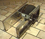
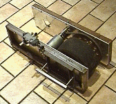
I made a start on removing the rear sets of wheels and replacing them with castors. I had sent an order for some caster to RS that were able to take a load of 120kg each. I could have chosen some with lower ratings, but I thought I would err on the cautious side because of the shock load the castors may get when the robot self rights and slams the whole weight onto the castors.
As normal the job of removing the rear wheels took a lot longer than I had anticipated. It took nearly two hours just to unbolt all the various bits and bobs before I could remove the two wheel axle units. Once I had removed the wheel and axle, I then had to shorten the chain, and route it differently around the motor sprocket. The new routing meant that I had to rotate the motor so that the chain didn't run against the mounting bolts. This entailed drilling new holes, and filling slots so that the motor could move, thus allowing the chain to be tightened. The old chain tensioner mechanism was then in the wrong position so would have to be moved as well.
By the end of the evening, I had made some progress on each axle bracket, but there was stilll a lot more work to do. But by 1.00am I needed to go to bed, and had to leave it for another day.
 |
 |
Sunday 17th March 2002
The task of removing the rear set of wheels and replacing them with castors was proving to be a bit more involved than I first thought. (What a surprise!)
Earlier in the week, I 'd taken the wheels away, and had to then shorten and re-route the chain over the motor sprocket. Shortening the chain was no problem, but on closer inspection I found that re-routing it meant it now just rubbed against the motor mountings. To stop this I had to rotate the motor 90 degrees, but then the chain tensioner was pulling in the wrong direction, so this would have to be moved too. This would involve cutting the axle bearing mounting brackets to fix the tensioner at the new angle, so if I was going to do that, I might as well shift the front wheel axle back a bit so that it ran nearer the centre of the robot. As one thing led to another I accepted that I might as well do as many changes as possible at this stage rather than make several minor alterations later.
| By the end of Sunday I had done a lot of sawing, filing, drilling and shifting of bits on the right hand side, but nothing on the left side. However it was good to see things were taking shape now. In terms of choosing the distance I needed to move the front axle backward, this was purely done on "gut feel". I wanted to keep a little weight on the back castors and have the front wheels just slightly ahead of the centre of the robot in the hope than dragging a bit of weight behind the Hog would make steering a bit more stable than trying to push the weight in front of you. Rather like the ubiquitous shopping trolley that is a lot easier to steer around the aisles by pulling it rather than pushing it. The proof of the pudding will obviously be in the eating later on when I next try it out in the school playground. |  |
Wednesday 20th March 2002
I managed to sneak into the garage for a few hours to work on the left hand side wheel assembly. By late in the evening I had shifted the wheel, cut the mounting bracket, re-routed the chain, and repositioned the chain tensioner. The only change I hadn't enough time to complete was making a support bracket for the end of the motor, which I left for another day.
Thursday 21st March 2002
I spent an hour in the garage making the motor support bracket for the left hand side. I also mounted the axle brackets back in the Hog, which meant that all I now needed to do was make the support brackets for the castor wheels.
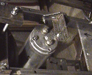 New motor mounting bracket |
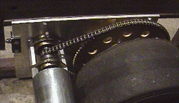 Re-positioned motor and tensioner |
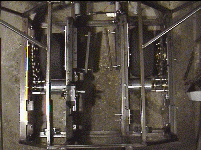 Both brackets in place |
Sunday 24th March 2002
I was away for a lot of the weekend, but towards the end of Sunday I managed to squeeze a few hours in the garage and worked on the castor wheel mounting brackets. These were fairly straight forward, being made out of angle iron, which I secured between two strips of 6mm aluminium plate at the rear of the axle mounting brackets. By the end of the evening I had both castor wheels in positions.
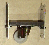 Castor on bracket and plates |
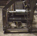 Rear view of castor |
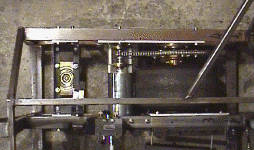 Top view of castor |
All that was needed now was to fit all the bits I had removed from the Hog back into the frame, and try the Hog out!
| I weighed all the parts and lumps of metal that I had removed during the process of swapping the two wheels for castors, and it came to about 11.5kg. There is obviously the added weight of the castors and their mountings, but the overall saving should have a significant impact on the type of cladding I can now use to cover the robot. | 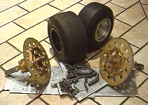 |
Good Friday 29th March 2002
Tried the Hog out in the school playground with its newly acquired castors. The results were very satisfying on several accounts. The battery life was substantially longer that the three minutes it lasted with the four go-kart wheels. I didn't time myself, but it felt like I was driving about for about 15 minutes. The manoeuvrability was vastly improved and I could turn the hog fairly easily.
There were only two mildly disappointing bits of news, and these were with the CO2 regulator and the gyro. I had to fiddle with the regulator again to keep the pressure down to 10bars. Initially it must have crept up to over 11 bars, which was when the pressure release valve cut in and let the gas escape out of the bottle. It seemed that almost each time I took the Hog out, I would have to adjust the regulator to keep it within the working range. I'm hoping this is just a bedding in process, but if not, I will have to look for a more resilient and stable regulator to take its place.
The other bit of bad news regarding the gyro was that although it was in-circuit, it was configured the wrong way around giving positive feedback rather than negative feedback. What this meant was that instead to keeping the Hog going steady in the desired direction, it would send it spinning around on the spot whenever it hit a bump, which was quite frequently in the playground. Luckily I had allocated a spare channel on the radio transmitter as a "gyro enable" channel, so could effectively switch the gyro out of circuit from the radio transmitter. With the gyro disabled, the Hog was still driveable, but tended to veer from the direction I wanted it to go fairly readily. After I'd flattened the battery and taken the Hog home, I dived into the controller box and found the gyro reversing switch that should make the gyro work for me, rather than against me in its next outing.
| In the evening I had another go at getting the buddy box going. After failing miserably to get the resistor values correct the first time, I bought a load of 50k pre-set potentiometers, and used these in a daisy chain to trim the action until the switches did what I wanted them too. I could plug the buddy box into the transmitter and switch it in and out of circuit from the main radio transmitter with a new switch I had put on the back of the unit, next to the buddy box connector. | 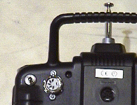 |
| When normal flipper and self righter controls were from a joystick that would open the flipper if pushed up, and would close the flipper if pushed down. However, for the buddy box I wanted to make the controls a little bit easier, so I used a three position, centre sprung switch for the flipper. For the self righting tail I used a momentary switch, so the tail would always be down if you let the controls go. The flipper had a sensor on it so that the controller could tell if the flipper was up or down, Just in case the flipper sensor mis-operated or got damaged in battle, I had an override switch that would effectively ignore the status of the flipper as given by the sensor, so you could force the pneumatics to open of close the flipper if necessary. | 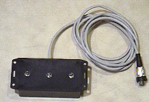 |
Saturday 30th March 2002
| I cut a scoop out of some 6mm aluminium plate for the flipper. This will make getting the flipper underneath objects a bit easier. | 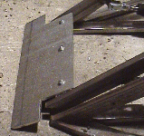 |
I pushed the Hog to the school playground again to try out the new scoop, and see how effective the gyro was, now that it was correctly configured. The results were very good. I could drive the Hog around the playground with it going exactly where I wanted it to go. As I had hoped, it was a bit more stable going forward because the driving wheels were in front, and the castors behind. When going backwards it was a little twitchy, but still went in the direction I wanted it to. It behaved very much as I had hoped it would, similar to pulling a shopping trolley around the aisles when driving forward, and like pushing the trolley when driving backwards.
The scoop too was working well and it was a bit easier to get under the go-kart tyres I had taken there for flipping practice. I did notice, however, that I was only getting a few flips out of each bottle recharge now, as my main CO2 gas supply bottle was getting low. By the end of the day it was no good at all and I had to drive to my local "air product" supplier to exchange it for a full bottle.
The buddy box was working well too, and my sons Jonathan and Robert both had a go at flipping practice while I drove the Hog around the playground.