June 2001
Saturday 1st June 2001
I finally got around to filling in the official Robot wars entry form today. I filled in all the sections but wrote across the front page "May not be ready for series 5, but please include in for the following series". This was the advice of one of the Robot Wars ladies who I spoke to on the phone. She suggested writing this on the front so that they would keep me informed of any rule changes or events taking place in the future.
Sunday 3rd June 2001
| Did a bit of work on bolting and wiring together the four MOSFET assemblies. Each "brick" is half an H bridge circuit and should be able to handle just over 500 amps. I still have my suspicions about how well and how long they will be able to maintain this level of current before either the MOSFETs self-destruct, or the wiring melts, so I will try the circuit out on lower powered motors first. | 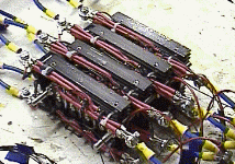 |
I have also just finished the latest version of
micro-controller software that decodes the serial data stream from the radio
receiver, and controls which MOSFETs to fire. It now checks to see if a gyro is
in circuit, and if so, uses the output from this to control the motors rather
that from the joystick direct.
I have updated the fail-safe features so
that it not only sets the channels to pre-set values when the signal goes, but
it also keeps a check on the quality of signal. If there are too many errors,
it assumes the signal is lost, and again sets the outputs to pre-set values. I
only discovered the need for this feature after I experienced interference from
my PC. I turned off the transmitter and instead of seeing the signal
disappearing, I saw the signal get erratic instead. What this would have
resulted in was the robot going loopy and out of control, rather than nicely
ramping down the outputs to and idle state. There are only a few more bits to
put together before I can check whether my new design works, or if I have been
wasting my time for the last few weeks!
Sunday 10th June 2001
| I built another assembly that will support the wheel bearings. This second one took a bit less time than the first one, but my welding could still do with a bit more practice. Only two more of these to build now! | 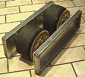 |
| I also fitted some suppression capacitors to the winch motors. There was not much room in the motor, but I managed to squeeze them in somehow. | 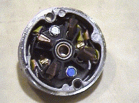 |
 |
Wednesday 20th June 2001
Did some off-load tests with the motor controller to check that
the H bridge pulses were okay. I spotted that there was a short period of
overlap during the on-off pulses that would mean both MOSFET would be on at the
same time, shorting out the power rails. This seemed to be due to a higher
MOSFET capacitance than I was expecting, so with a nifty change of a few
resistors I managed to bring the overlap down noticeably. With this done I was
able to try out the controller on one of the smaller motors. I used a small
lead from the battery to the MOSFETs so that it would act as a fuse should the
current drain be too great.
I needn't have worried as the circuit behaved
itself and I could control the motor okay. I could hear the MOSFETs buzzing
slightly while they were working, which I assumed was due to the very slight
remaining overlap of pulses. Nothing got too hot though, but I may need to
change a couple more components when I start driving the winch motors and using
full sized cables from the battery to the MOSFETs.
Sunday 24th June 2001
Three wheel bearing support assemblies down, and one to go. My
welding is improving, but still a bit inconsistent, however I am getting faster
at making the assemblies now.
| I also tried out the motor controller on a winch motor after having first put full sized cables in circuit and tried it on a small motor. To my relief it worked fine. The winch motor had quite a lot of torque, and I had to hold it down on the workbench to stop it jumping about as I wound the power up. After a few minutes running all seemed okay. Both the motor and MOSFETs were getting comfortably warm but not too hot to touch. I wondered how hot they would get under full load, particularly as the winch motors are not supposed to be run continuously without a cool down period. I noticed that both sets of H-Bridge MOSFETs were getting warm, even the ones without a motor connected to them. I assume this is because of the slight remaining overlap in on-off pulses, so I will need to look into reducing this further. | 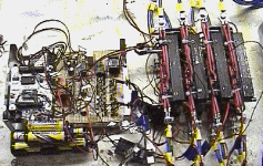 |
Wednesday 27th June 2001
| In an effort to solve (or at least reduce) the on-off pulse overlap problem I was having with the motor controller, I bought another type of opto coupler for between the micro-controller and the gate driver stage of the circuit. This opto had a higher gain and therefore allowed me to switch the gate driver stage a bit harder and faster. With an additional change of a few resistors, the pulse overlap was much reduced. | 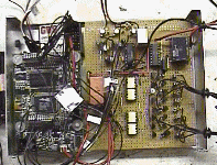 |
The MOSFET stage now ran a lot quieter and cooler, and the
motor ran a lot smoother. The only down side was that the motor ran a bit
warmer now, presumably because more power was being switched through to it
rather than being shunted out by the overlapping pulses. Half an hour after I
had run the motor, it was still quite warm to the touch, and this was when the
motor was running without any load!
Front left view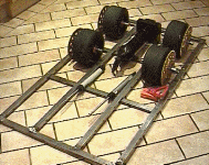 |
Front right view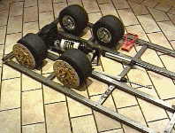 |
Front view 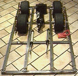 |
Rear view 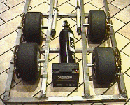 |