January 2002
Wednesday 9th January 2002
I was coming to a lull in the robot build because I had run out of various materials for building the chassis and body. I also hadn't yet got the pneumatic components in my sticky hands, although I had been talking to a number of people over recent weeks and picking their brains. I therefore decided to take a day off work and kill several birds with one stone and do a grand tour of the various suppliers.
I started with Ian at Southern Steel who had ordered me some more steel box section, and some aluminium and steel angle iron. I spent some time talking to him about the self-righting arm, and he suggested using thick aluminium plate made into a T section. He thought that my initial idea of using a box section might not work because it would not be strong enough and could buckle under the load of the robot. He pointed me towards a local scrap metal dealer who he said would be able to sell the size I wanted at a much lower price than he could offer, and he was right! I found a metre square piece that will be ample for the job.
I also asked him about welders, since I found my welding was a bit inconsistent. He said I really should consider buying a MIG welder, and directed me to a supplier 50 yards down the road, which was the place he had bought all his professional welding gear from. After talking the pros and cons over with the manager for half and hour, I bit the bullet and bought a 130 amp gas MIG welder.
 |
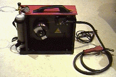 |
. I had some reservation about whether I should have bought it because I already had an arc welder, so when I got it home I had a trial go. WHAT A DIFFERENCE! I couldn't believe how easy it was to use the MIG compared to the arc welder. Striking the arc was no problem. You pull the trigger, the wire comes out of the torch, touches the work piece and off you go. The bead seemed to suck itself onto both surfaces of the joint. All the problems I had with the arc welder such as welds only sticking to one surface didn't happen. And because there is no "slag" on the weld, if you accidentally burn a hole in the metal you just go back over the section again and fill it in. If anyone is considering buying a welder, I would strongly recommend they choose a MIG. The bad points are having to buy gas bottles and wire, and the thickness of metal you can weld is only about 4mm with a 130amp unit. With my existing arc welder I can weld thicker metal if necessary, but for virtually all the items I will weld on the robot, I can now do a consistent weld with the MIG unit. The hassle of gas is therefore a small penalty to pay. And on top of that, I can weld aluminium and stainless steel too, provided I get the appropriate wire and gas bottles.
I then went to Belsales, who are a supplier of paint ball gun parts. I had spoken with Steve over the phone about bottles, regulators and filler units, and intended to see them for myself before buying. The regulator was particularly compact, and looked like a tube that screwed directly onto the bottle top.

The paint ball bottle had an American thread on the top, and was a bit smaller than the CO2 fire extinguisher I had intended using. On the other hand it would be lighter. If the paint ball bottle did prove to be too small, there were adapters I could used to connect the extinguisher to the regulator instead at a later date.

From left to right, the components are (1) bottle with anti-siphon tube inside (see below), (2) adapter connecting the bottle to the regulator, (3) the regulator itself, (4) adapter allowing standard pneumatic fitting to be screwed into the regulator. The regulator pressure can be adjusted from a screw that you can access once the bottle-to-regulator adapter is removed. You have to turn the screw a bit and then connect the regulator back on the bottle with a gauge connected to it to see what pressure it is working at. It's a bit fiddly, but that seems to be the penalty you pay for having such a compact regulator.
Steve told me that the regulator would tend to shut off when liquid CO2 entered it, and should therefore reduce the chance of any liquid getting into other components and damaging them. There was also an anti-siphon tube within the bottle that reached half way down, and curved towards the side, with only a small gap between the end of the tube and the bottle. The idea is that because the bottle is only ever about a third full of liquid CO2, the tube will be above the top of the liquid when it is in an upright position. If the bottle is on its side in the robot, you position it such that the anti-siphon tube points upwards, so liquid won't get through. I'm not sure quite what happens when the robot it inverted, but I think I will try to position the bottle inclined at about 45 degrees, and get the best of both worlds. Steve gave me a good price on the items (virtually cost price), so you will now find Belsales on my sponsors page.
| The final piece of pneumatics I bought from Belsales was a filling kit. Here you see it connected to the bottle directly. The end with the two taps connects to a CO2 bottle, which should NOT be a drinks type CO2bottle. This is because these type of bottles don't have a tube inside that descends into the liquid. When you refill a bottle for the robot you actually want liquid to be transferred from the main bottle to the robot bottle. Drinks type bottles don't have the tube so you won't get much liquid, therefore you can't fully charge your bottle. The filling process must also be done carefully, and should be done with the bottle cooled to get a full charge. To do thing Steve told me to slowly put some CO2 into the bottle and then slowly let it out again. The process of the CO2 gas expanding will cool the bottle. A point to note too is that you can't tell how full the bottle is by measuring the pressure. The pressure is mainly determined by the temperature of the bottle, not the volume of CO2 in it. You have to weigh the bottle to see if it is full or not. The bottle I bought was a 20oz bottle, so you have to weigh it empty and then weigh it again after filling. If it is 20oz heavier than when empty, then it is full! | 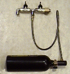 |
My final point of call today was Southern Pneumatic. I spent quite some time with Peter going over the bits I had just bought from Belsales, and the design I intended to use for the robot. We ended up with a list of items, some of which Peter would have to chase up over the next few days. I finally left for home, happy that I had made a lot of progress in getting parts. I hope to make a fair bit of progress on the pneumatic front over the coming weeks, and with any luck be able to mount the batteries and motor controllers within the body of the robot too. At that point I may be able to actually run the robot along the ground under its own power!
Sunday 13th January 2002
|
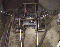
With my new supplies of metal I welded a set of "ears" to the robot. These are to prevent the Hog being stranded on its side by forcing the hog to either roll back onto its wheels or go right over on to its back. The ears looked a lot bigger than I imagined they would, but they seemed to do the trick. I couldn't get the robot to stay on its side unless I wedged blocks of wood under it!. It meant too that it was quite awkward to manhandle now with the ears sticking out so far and I couldn't move it into the kitchen where I normally take photos from. The picture here is from within the garage. |
 |
I measured the weight of various parts of the robot just to see how close I was to the 100kg limit. The results were as follows:
| Two batteries | 12kg |
| Pneumatics I have to date | 7kg |
| Radio gear and speed controller | 1kg |
| Chassis | 58kg |
| Total | 78kg |
This leaves me about 22kg for the flipper, the self-righter, any armour cladding I want to put on, and any other miscellaneous bits and bobs. All in all not a lot to spare. I know I can save about 6kg if I only use one battery, and I estimate that I could cut out about 5kg of aluminium plate from the wheel assemblies, but this will leave them a bit weaker than I would like. This makes me seriously consider cladding the Hog in fibre glass, and only putting thick metal plate where absolutely necessary on the body.
Saturday 19th January 2002
|
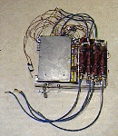
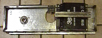
With the new aluminium angle iron I had bought recently, I went about making a tray to support the MOSFETS bricks and the motor controller box. There was just enough room to mount these side by side between the two axle brackets, leaving a small gutter between them in which I could place the two battery packs supplying the radio receiver and micro-controller. |
 |
Mounting these on the top of the axle brackets like this means that they are located in the physical centre of the robot. There is space between them and the surrounding body frame, which means that any axes attacks stand a good chance of being held away from the vital components as their arms hit a body cross member. There is always the chance that a well-placed axe blow might get through and destroy the controller, but hopefully the chances are reduced by having this "safety void".
I had a good think about the mounting method I would need to secure the two batteries in place. I can remember the Tornado team telling me that they gave a good deal of thought to how to restrain the movements of these heavy components in all six directions. E.g. forwards, backwards, left, right, up, and down. The most sensible structure to attach them too seemed to be the axle brackets, so after a bit of head scratching I came up with a simple frame made up of angle iron that holds the batteries secure in five directions. I then bolted a bar to this framework to complete the battery bracket.
 |
 |
At this point I had one battery bracket bolted on, the controller secured in place, and the safety link and power solenoid bolted on the chassis too, so couldn't resist checking that nothing has suffered during my manhandling of all the electronics. I put the robot on blocks to stop it moving, and then ran up the motors. Nothing seemed to have suffered, but after a while of running the motors at full speed on the single battery, they slowed down in that all too familiar exponential way! Conversely the MOSFET bricks started to warm up exponentially and it didn't take me long to realise that the high-side DC-DC converter was switching off. I had chosen a 5 volt "in" and 12 volt "out" converter so that I had some headroom if the battery voltage varied. My first instincts were that the battery voltage had dropped too much and the crude resistor-zener diode network supplying power to the DC-DC converter was then too low.
I put the trusty voltmeter across the battery as I tried the motors again, and watched the motors spin at full speed for a while before slowing down as the battery voltage sagged to 8 volts! Driving the two motors from one battery was too much for these batteries to maintain full terminal voltage, and my crude supply to the converter couldn't maintain enough voltage.
The solution is to replace the resistor-zener diode network with a voltage regulator that can maintain the supply to the DC-DC converter as the battery voltage sags. Paging through the RS catalogue, I found a suitable regulator at a cost of 34 pence, which is probably cheaper that the resistor-diode components already in circuit! After a quick surf of their web site I sent an order off, and should be able to modify the circuit during the coming week.
Wednesday 23th January 2002
The new 5 volt regulator arrived from RS so I pulled the controller board apart and replaced the existing resistor-zener diode network with the regulator. I also finished the second battery mounting bracket and bolted this in place on the other axle bracket. With the robot mounted on wooden blocks I ran the motors up, and to my delight the new power regulator did a fine job. The motors didn't slow down during the few minutes I ran them for, and the MOSFET bricks were only slightly warm.
Sunday 27th January 2002
Not too much has happened over the last week in terms of physical additions to the robot, but I did spend a fair time talking to various people about materials to use on the body shell. Wood is surprisingly light, volume for volume compared to metal sheet so I could use, say, a quarter of an inch thick sheet on the body. I could also use polycarbonate, which too is light and strong compared to metal sheet. Titanium is the exception, but is quite expensive and difficult to machine. Another suggestion was a material called Dibond, which is apparently a sandwich between polycarbonate and aluminium, and it very strong and light. I haven't made up my mind what to use yet, but have fired off a number of e-mails to various suppliers to see what deal I can strike.
I thought I should start to raise the Hassocks Hog's profile a bit and foster some local support so I asked a few of the local Hassocks village web sites if they could put a link to my site on their web site. They all duly obliged, and I even got a home page mention on one, instead of being hidden several clicks away on their "links" page.
A veteran Radio control enthusiast Denis suggested that I should consider splitting the robot controls between two controllers. Concentrating on driving will be enough of a job without having to think about the weapons as well. It was a valid point, and many of the best roboteers had two people operating the robots at once. The normal "training" connector on my Futaba transmitter unfortunately won't be able to help because it passes the whole control from one transmitter to the other. What I need is to transfer just some of the controls over, so I will have to dive inside the unit and extricate the relevant wires to a remote controller unit. I fired off an email to Futaba asking for a circuit diagram for the transmitter so that I won't have to do too much guess work, but as yet they haven't sent anything back.
| Over the weekend I did some work on the self-righting tail. I build up the rear support and made a couple of hinge brackets out of 3mm metal plate. I made it fairly strong because I thought it would take a fair bit of bashing when the robot is flipped over. I also made a cardboard tail just to see what it would look like and to get a feel for the size of the T section I would need. | 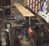 |
| Next I made a set of hinges for the front flipper. Again I made them out of 3mm metal sheet, because I didn't want them to bend while flipping any opposition. I only hope they don't add too much to the weight of the robot! | 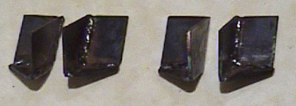 |
Thursday 31st January 2002
A parcel full of parts arrived from Southern pneumatics. After getting all the bits out and laying them on the floor next to my schematic diagram I manage to piece together the jigsaw of what connected where. Not unexpectedly there were a few items that I still needed to get before it would all work! These were union fittings for the paint ball bottle, which were an American thread termed "NPT". All the other unions were British Standard Pipe Thread (BSPT). I talked over the missing parts with Peter, and he said he would post the parts he could get hold of over the next few days.
Meanwhile I browsed through the RS components catalogue for some of these strange America unions and ordered a selection of ones that looked like they might fit.
Below is an updated diagram of the Hog's pneumatics. (Internet Explorer users can click of the components to see a photo of the actual parts. The pop-up windows will close automatically after a few seconds.)

|